Faster tooling. Stable geometry. Lower total cost.
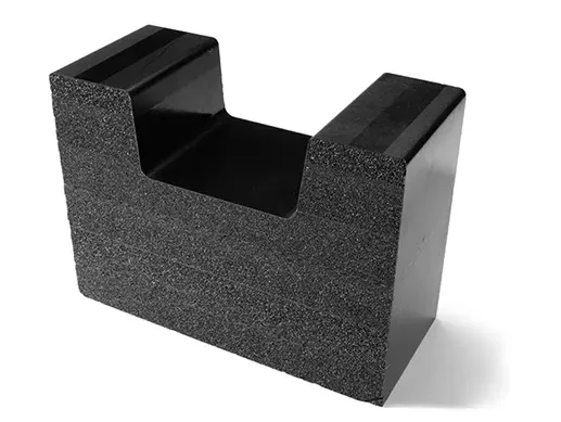
CFOAM enables a different approach to composite tooling. Instead of machining heavy metal and managing thermal inertia, engineers can build dimensionally stable, lightweight tools that machine easily, and scale without penalty.
For carbon fiber layup, mandrels, and cure tools, CFOAM removes many of the constraints that have historically driven up cost and lead time.

Why Engineers Choose CFOAM
Composite Tooling with Clear Benefits
Low CTE Where It Matters
CFOAM maintains a coefficient of thermal expansion (CTE) near 2.8 ppm/°F, allowing tools to track composite parts closely through cure cycles. This reduces residual stress, improves dimensional accuracy, and minimizes iterative rework.
Machinability Without Penalty
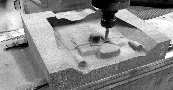
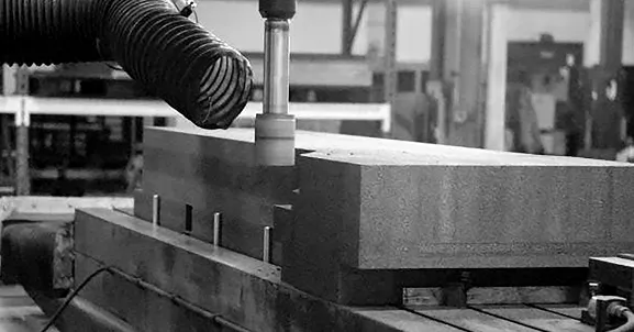
CFOAM machines easily. Large billets can be bonded, shaped, and quickly modified. Design changes that would be cost-prohibitive in metal become routine.
Lightweight at Scale
At roughly 30 lbs/ft3, CFOAM tools are dramatically lighter than metal equivalents. This simplifies handling, reduces fixture requirements, and enables larger tool geometries without infrastructure changes.
Cost Advantage Without Compromise
Prototype tools have been demonstrated to have significant cost and lead time savings than Invar, while maintaining performance in real composite manufacturing environments.
The Key Technical Advantage
A Different Tooling Physics
Conventional Tooling
Dimensional Stability

Thermal Responsiveness
Manufacturability
Most tooling materials force a tradeoff between dimensional stability, thermal responsiveness, and manufacturability.
CFOAM Tooling
Low CTE
Low Density
Machinable Structure
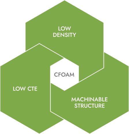
CFOAM combines low CTE (dimensional control), low density (low thermal inertia), and machinable structure (fast iteration) without tradeoffs.
For tooling programs limited by lead time constraints, rework, or modification cost, CFOAM is not simply a material substitution. It can change the cost, schedule, and flexibility profile of the entire tooling workflow.

How CFOAM Tooling Is Built
Proven Tool Construction Workflow
Billet Formation
Blocks are bonded into near-net shapes, enabling large tools without material constraints.
Rough CNC Machining
Geometry is cut efficiently with standard tooling.
Surface Build-Up
Carbon prepreg or a carbon filled epoxy resin are applied to create either a durable production style tool face, or a rapid prototype production option.
Autoclave Cure
The surface layer is consolidated under production-like conditions.
Final Machining and Finishing
Precision geometry is achieved, followed by sealing and polishing for release-ready surfaces.
This hybrid approach combines the structural benefits of CFOAM with the surface performance of composite tooling systems.
The prototype version is perfect for developmental programs as this tooling method is easily modifiable to support evolving engineering. It can then be “recycled” to convert it to production tooling by using the same base CFOAM material, then wrapping it with carbon prepreg adding durability with cost and lead time savings by repurposing the prototype version.
Performance in Practice
Validated in Composite Tooling Applications
CFOAM has been used in hundreds of tooling builds, including complex geometries that would be difficult or costly in metal.
- Large, multiple piece breakdown mandrels
- Stable performance through repeated cure cycles
- Reliable part release with standard surface treatments
- Comparable surface hardness to traditional composite tooling systems
CFOAM vs Traditional Tooling Materials
Where CFOAM Wins: Performance Benefits
CFOAM vs. Invar
CFOAM vs. Aluminum
CFOAM vs. Composite Tools (all-prepreg)
CFOAM vs. Invar
- Lower cost
- Faster machining
- Faster thermal response
- Much lower weight
- Faster lead times
CFOAM vs. Aluminum
- Lower CTE
- Better dimensional stability across cure cycles
CFOAM vs. Composite Tools (all-prepreg)
- More stable core structure
- Easier large-scale machining
- Better repeatability in thick sections
Design Flexibility
Engineered, Not Just Selected
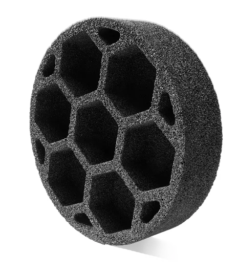
CFOAM is not a single fixed material. Density, pore structure, and surface treatments can be tailored for each application. This allows engineers to optimize stiffness vs weight, permeability and vacuum integrity, surface integration strategies, and thermal response characteristics.
The Key Perspective
Tool performance is not just about the base foam. The surface system and integration method determine final performance. CFOAM enables more control over that system than traditional tooling materials.
Practical Considerations
A number of well-understood processes are already built into standard CFOAM tooling workflows. Such as surface sealing is required for vacuum and finish quality, and bonding and surfacing processes should be controlled for durability.
Where CFOAM Fits Best
| CFOAM delivers the most value when: | CFOAM is especially effective for: |
|---|---|
| Tools are large or complex | Carbon fiber layup molds |
| Iteration speed matters | Mandrels |
| Weight or handling is a constraint | Autoclave tooling |
| Prototype-to-production transitions |
Is CFOAM Composite Tooling Right For You?
CFOAM is not just a substitute for metal tooling. It enables a different design and manufacturing approach. If your current tooling strategy is limited by cost, weight, or thermal performance, it’s time to rethink these tooling constraints. CFOAM is worth evaluating early in the design process.
